Serial.println("servo motor angle 90 deg"); Serial.println("servo motor angle 120 deg"); Serial.println("servo motor angle 150 deg"); else if(results.value==6338) // if volume UP button is pressed, if(motor_angle<150) motor_angle+=5; // increase motor angle, servo1.write(motor_angle); // and move the motor to that angle, else if(results.value==6292) // if volume down button is pressed, if(motor_angle>0) motor_angle-=5; // decrease motor angle, servo1.write(motor_angle); // and move the motor to that angle, irrecv.resume(); // again be ready to receive next code, IR remote controlled DC servo motor using Arduino, DIY IR Remote and IR Remote controlled LEDs, All About Servo Motors and Servo Motor Tester. The task that the servo should perform is: This is a nice code.but can you use normal IR-sensor-transmitter couple instead of the sharp sensorSharp sensor cost 2.5 $ but the normal one cost 20 cents..for one who makes a lot of robots, that makes a differencebut how far the same code will function on a pair of IR transistor and receiver?? For performing the specific operations we are using if conditional statement. Connect the VCC wire of the servo motor with the 5 volts pin of the Arduino and the GND wire of the servo motor with the GND pin of the Arduino. It must exhibit a degree of intelligence, such as decision-making, If an object is detected, turn the servo motor 10 degrees, If there is no object detected, turn the servo motor 150 degrees, If an object is detected, turn the servo motor 10 degrees and turn on the LED, If there is no object detected, turn the servo motor 150 degrees and turn off the LED. The project uses normal set top box (STB) IR remote, TSOP IR sensor and Arduino UNO board. They are commonly used in object detection systems. That means when any digit button between 1 to 5 is pressed, the motor will move to that specific angle. One of the very well common range sensors are the infra red(IR) distance sensor, also known as Sharp sensors referring to the company that makes them. Any digital input pin can be used. Use an ordinary TV remote to control your next project, NPN Bipolar Transistors (PN2222) - 10 pack, Breadboard-friendly RGB Smart NeoPixel - Pack of 4, "An expert is a person who has made all the mistakes that can be made in a very narrow field". What would you like me to cover next?! There are three circuit diagrams given in this post so that you can make any of them as per your choice. The loop function gets an IR code and passes it to a switch statement depending on its value. Click to share on Twitter (Opens in new window), Click to share on Facebook (Opens in new window). you ought to understand that the remote sends Infrared (IR) signals, thus we are going to learn the way to receive and skim these signals victimization Arduino. The example as presented here should work okay on Arduino Uno or Mega however if you are using Arduino Leonardo, Arduino Micro, Arduino Yun or other ATmega32u4 based systems, you will have to make a slight modification to IRLib. Follow the steps for wiring in the pictures. Especially normal, readily available, hand held IR remote which we can find in all most all the homes for TV, AC, music systems, DVD or even for STB (set top box). Please do follow us i.e #learnelectronicsindia to get daily updates about new blogs, videos, courses, quizzes, and contests. (LogOut/ }, LIGHTNING COUNTER WITH LED DISPLAY(COMMON ANODE), PROPORTIONAL CONTROL STEPPER WITH IR DISTANCE, TWO STEPPER MOTOR COTROLLED BY IR DISTANCE, WRITING STRING ON ARDUINO EEPROM VIA SERIAL MONITOR, SETUP BLUETOOTH MODULE AS MASTER OR SLAVE, SWITCH BY REMOTE AND SEVEN SEGMENT DISPLAY, ANALOG READ WITH 595 SEVEN SEGMENT LED DISPLAY, AUTO SWITCH WATER PUMP BY SENSOR MPX5010DP, BODY HEIGHT MEASUREMENT WITH VL53L0X SENSOR, CONTROLLING BIPOLAR STEPPER WITH IR REMOTE, LIGHTNING COUNTER WITH 595 SEVEN SEGMENT DISPLAY, PIR SENSOR HC-SR501 THIEF ALARM WITH A6 GSM MODULE, THERMOHYGROMETER BY WET AND DRY THERMOMETER, THERMOHYGROMETER BY WET AND DRY THERMOMETER WITH LED MATRIX, WATER DEPTH MEASUREMENT MPX5010DP WITH LCD. If you do not know about servo motor and motion sensor (pinout, how it works, how to program ), learn about them in the following tutorials: Image is developed using Fritzing. Then declare the pin modes for each input r output pin that we are using. i make automatic railway gate control. We take care of that special case by storing the previous value at the bottom of the switch statement so that if we get a repeat code we can substitute it the next time. That protocol has a unique feature that allows you to see if the button on the remote has been held down to send repeated instances of the same value. Connect 10K potentiometer as shown in the image. Rotate the motor to a specific angle like 30o, 60o, 90o, . (LogOut/ Similarly when volume down button is pressed, the motor angle decreased by 5o means if its on 90o, it will move to 85o and likewise. void setup() Serial.println("servo motor angle 60 deg"); servo1.write(motor_angle); // move the motor to 60 deg, else if(results.value==2215) // like wise for all digit buttons. Also, do check out more articles on Arduino and Raspberry pi published by us. This Sharp sensor has 3 wires: Black for ground, Red for 5volts, and Yellow for data. It must be able to obtain information from its environment. Make sure that the components are working properly and of the correct values. The sensor TSOP1738 has 3 terminals (1) Vcc (2) Gnd and (3) output. Will cover that later in the section on sending. We also have a servo with three wires. Now make the connections between the 162 LCD module and analog pins of the Arduino. What if we want to control the servo motor using remote? As shown in figure, the circuit is built using 2 components only an Arduino board and IR sensor.  When volume up button is pressed, the motor angle increased by 5o means if its on 30o, it will move to 35o and likewise. We hope that you liked this project and understand it as well. If button 2 is pressed then it turns by an angle of 90 degrees and after a delay of 1000ms, it returns to its initial position. Circuit connection involves the following steps: The output pin of the IR sensor is connected to digital pin 5 of the Arduino board. It is a wireless remote control device that is used to operate audio, video, and other electronic equipment in a room through the detection of IR radiations. SmartMatrix Remote Controlled LED Art Display. infrared sensor ir module obstacle arduino robot using avoidance led gate railway automatic control detection connection pakistan sensors jl 1pc We will build on the previous project by adding 1 LED. ArduinoGetStarted.com is a participant in the Amazon Services LLC Associates Program, an affiliate advertising program designed to provide a means for sites to earn advertising fees by advertising and linking to Amazon.com, Amazon.it, Amazon.fr, Amazon.co.uk, Amazon.ca, Amazon.de, Amazon.es and Amazon.co.jp. unsigned long last = millis(); By default it uses TIMER2. The Arduino has analog output through which it generates PWM that is used to rotate servo motor at a specific angle. I have used set top box (STB) remote that has many buttons like 0-9 digit buttons, volume control buttons, channel up/down buttons, arrow key buttons etc. Project By - Debangshu Sarkar , Edited By - Sowmya. Share with your friends to help us spread the tutorial! It was last ####include
  We are using an IR remote control for sending the signals wirelessly and at the other end we connect a TSOP IR receiver module. A #breadboard is a construction base for building electronic circuits. You may need to add an external 5 volt supply. Hey geeks, we are back with another new post on Arduino UNO. The wiring for the IR receiver and servo motor are shown in pictures. Later in the file we copy this value to also be used as the receiving timer. NOTE: The above illustration shows the receiver on pin 11 however the sample code uses pin 2. We appreciate it. head.attach(5); if (sensorValue0 < 100) The given project demonstrates how to move servo motor at specific angle using IR remote (like TV, DVD, AC, STB etc) with the help of Arduino. After deciding the buttons, next is to decode the codes of these buttons. So the first step is to use the built-in servo library, by writing: Then we named our Servo object as Serv, by typing in.
In this example we will control the servo using an IR remote. The new angle position is displayed on serial monitor. head.write(90); The messages displayed on serial monitor as IR remote controlled servo motor and servo motor angle 0 deg, Now as button 1 is pressed from remote motor will move to 30o and likewise when button 2, 3, 4 or 5 is pressed motor will move to the desire angle 60o, 90o, 120o or 150o. If button 1 is pressed then the servo turns by an angle of 45 degrees and after a delay of 1000ms, it returns to its initial position. Thanks for sharing informative content. we always keep eye on upcoming technologies and we make sure we are always updated. Open Arduino IDE, select the right board and port, Copy the above code and open with Arduino IDE. To know more about the Arduino UNO, refer to this article. robot obstacle avoidance arduino code robotshop community In this #DIY project, will learn how to control a servo motor with an IR remote by interfacing it with #Arduino using #Tinkercad software. The statements will execute only if the base condition is true. The ground pin of the servo motor is connected to the ground. ir It has many holes into which circuit components like ICs and resistors can be inserted. Make the connections properly and upload the code according. For the actuator, we will use the Tower Pro SG90 micro servo motor, and of course, for the brains of our robot, we will use an Arduino board. You can find more information on the standard Arduino Servo library here. The red wire is +5v. Become a Master of the Fade In Fade Out Effect (Arduino Style), 3 stacks x 3 shots: an Arduino Game Prototype, Taz the TRASHmanian Devil: A DIY Arduino Trash Bin, The Fortune-Telling Skills of Robby the Robot, Home-y Organizer: An Arduino Servo and Sensor Project. If, for any reason, you would like to unsubscribe from the Notification List for this product you will find details of how to do so in the e-mail that has just been sent to you! First of all, connect the OUT leg of the IR receiver with the digital-4 pin of the Arduino. When you press the buttons on the IR remote the arduino servo control will start changing its position. In this article we are going to teach you that how you can make your own arduino servo control remote system. Now that we have both the servo and the IR sensor, go ahead and mount the sensor on the servo so it will rotate it and give us a precise information about the surroundings. * This example code is in the public domain, * Tutorial page: https://arduinogetstarted.com/tutorials/arduino-motion-sensor-servo-motor, // Arduino pin connected to motion sensor's pin, // Arduino pin connected to servo motor's pin, // create servo object to control a servo, // attaches the servo on pin 9 to the servo object, Arduino - Button - Long Press Short Press, Arduino - Potentiometer Triggers Piezo Buzzer, Arduino - Potentiometer Triggers Servo Motor, Arduino - Servo Motor controlled by Potentiometer, Arduino - Ultrasonic Sensor - Piezo Buzzer, Arduino - Ultrasonic Sensor - Servo Motor, Arduino - Temperature Humidity Sensor - LCD, Arduino - Temperature Humidity Sensor - OLED Display, Arduino - Display Temperature from LM35 Sensor on OLED, Arduino - Display Temperature from LM35 Sensor on LCD, Arduino - Cooling System using DHT Sensor, Arduino - Cooling System using DS18B20 Temperature Sensor, Arduino - Button Controls Electromagnetic Lock, Arduino - Door Lock System using Password, Arduino - Controls 28BYJ-48 Stepper Motor using ULN2003 Driver, Arduino - Controls Stepper Motor using L298N Driver, Arduino - Log Data with Timestamp to SD Card, Arduino - Door Open - Send Email Notification, Arduino - Temperature - Send Email Notification, Example - 04.Single Blink Change Frequency, Example - 05.Multiple Blink Without Delay, LDR Darkness and Light Detector Sensor Electronic Circuit, Tutorial using serial LCD screen make Arduino speed curve recording, please give us motivation to make more tutorials, Arduino Code - Motion Sensor Controls Servo Motor, Motion Sensor and Servo Motor on Commercial Products. } The setup function attaches the servo, enables IR input, and initializes several variables. Change), You are commenting using your Facebook account. Join the GND wire with the GND pin of the Arduino. For example, if you press button 1 on the IR remote then the servo motor will rotate to a specific position. In this project, we will try to move the servo shaft if an object is detected. Jumper wires are a group of electrical wires, with a connector at each end, which is used to interconnect the components of a prototype circuit. Since we have data wire, we need a microcontroller unit to analyze that certain input from the sensor, in this case well be using the Arduino(uno): But having an IR sensor on its own is not that helpful, once you detected an object in-front of the robot, you need to know which direction to head for that is clear of obstacles, therefore, a stationary IR sensor does not provide that help, we need to rotate it using a servo motor: The Arduino comes with a library for controlling a servo with pretty straightforward examples to make it easy to learn. Connect the signal wire of the servo motor with the digital-3 pin of the Arduino. Attach the positive power leg of the TSOP IR receiver with the 5 volts pin of the Arduino. arduino inventor to get daily updates about new blogs, videos, courses, quizzes, and contests. Serial.println("servo motor angle 30 deg"); servo1.write(motor_angle); // move the motor to 30 deg, else if(results.value==6308) // if digit 2 button is pressed. Initially, the servo motor is in the 0 position. This page (Controlling a Servo with IR) was last updated on Aug 01, 2022. If button 4 is pressed then it turns by an angle of 180 degrees and after a delay of 1000ms, it returns to its initial position.  document.getElementById( "ak_js_1" ).setAttribute( "value", ( new Date() ).getTime() ); Enter your email address to subscribe to this blog and receive notifications of new posts by email. After that join the OUT leg of the IR receiver with the digital-4 pin of the Arduino. Upload the program into arduino micro controller and connect IR sensor as shown in figure. There is one bit of overhead we need to take care of because we are using NEC protocol. First see the circuit diagram followed by its description and operation.
 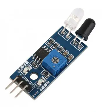 { You can also read more articles on IoT and basic electronics. Possible Side Effects For Amoxicillin levitra coupon free trial What Is The Average Price For Viagra? If you're using Leonardo and you later use IRLib to send IR signals you will need to make note of the numbers after these defines. Then join the negative power leg with the GND pin of the Arduino. Also the servo connection is displayed in the image in this post. If you buy the components through these links, We may get a commission at no extra cost to you. As we know when any button is pressed from remote, it will send one code and based on this code the action is performed. else we want more information about networking concepts in embedded system. First we have to decide, which are the different buttons of IR remote, that we will use to rotate servo motor. (LogOut/ Note: Please upload the code to the Arduino. head.write(180); Join the positive leg of the second LED with the digital-9 pin of the Arduino. Pushing the up or down arrow buttons will not have any visible effect but it will change the speed of movement you push left or right. Below is a version of the servo.ino sketch from the "IRLib2/examples" folder. please send me programme. All rights reserved. For control servo motor you just need to press a button on the IR remote. Facebook | LinkedIn | Instagram | Youtube | Website | Gmail, Portfolio link - www.learnelectronicsindia.com/team/akshara-ganeshram, To know more about the Arduino UNO, refer to. Here is an illustration showing how to wire up the devices. Note down the codes of required buttons like I have noted the codes as per following table : In the arduino sketch above codes are used corresponding to button pressed to perform action as per previous table. The serial monitor also displays servo motor angle position as servo motor angle xx deg. After that attach the OUT leg of the IR receiver with the digital-4 pin of the Arduino. The numbered buttons from zero through nine move the servo to 10 different fixed positions at 20 intervals. Connect the negative legs of all three LEDs with the GND pin of the Arduino via a 220 ohm resistor. Its Vcc terminal is given 5 V from board and Gnd terminal is connected to ground of board. updated on Feb 26, 2015. Join the positive power leg of the TSOP IR receiver with the 5 volts pin of the Arduino. Sensor output is connected digital input pin 12 of arduino board, Analog output pin 5 is connected to servo motor signal input pin to drive the motor, The servo motor is given external 5 V supply, Fig. The Arduino servo library also uses hardware interrupts using TIMER1. (irrecv.decode(&results))); // wait until no button is pressed, if (irrecv.decode(&results)) // when button is pressed and code is received, if(results.value==2210) // check if digit 1 button is pressed. Copyright 2021 ArduinoGetStarted.com. First, we declared the data type of each variable and then assign their values. Then attach the positive leg of the second LED with the digital-9 pin of the Arduino. If you're using a different remote, you will have to collect information about your codes for various buttons using dump.ino and modify the sketch with the proper protocol name and codes. If you have any doubts related to this post then feel free to use the comments section given below. With this simple Arduino project, you can servo motor using a remote control. In this lesson, we are going to learn the way to manage a servo motor with the remote. ALL RIGHTS RESERVED. IRLib uses your Arduino's built in hardware timers to generate an interrupt every 50s so it can poll the input pin to see if it has changed. Connect the positive leg of the third LED with the digital-10 pin of the Arduino.
  For our sensor, we will use the basic HW-201 IR sensor. void loop() Like, we can move the motor to specific angle like 30o, 60o, 90o etc or we can linearly increase or decrease motor angle using IR remote any IR remote. So, our customers get the best and the output that stands in the international market. So let us see how this is done. We use the IR receiver to read IR signals from the remote control. However the ATmega32u4 processor does not have TIMER2 so IRLib defaults to TIMER1 on systems using that processor. If youre searching for comfort and dominant your electronic devices remotely, you may notice you would like during this instructable. We will substitute the Sharp IR sensor with the HW-201 IR Sensor. When power is applied the motor moves to 0o. Now let us see the actual operation. The program creates a receiver on object, a decoder object and a servo object. } Anyone can use any type of IR remote. #IRsensor is an electronic device that detects IR radiations in the physical world. Your connections are complete now. Each case of the switch statement handles a different function moving the servo as needed. Although, you can use any sensor available at your disposal. This is how this project should work: The code is basically the same as the previous project except we just added some codes for the LED. Just he has to change the remote codes in the Arduino sketch (program) for the remote. (adsbygoogle = window.adsbygoogle || []).push({});
. servo engineersgarage The holes in the terminals are connected horizontally and the holes in the middle are connected vertically. We can adjust the speed that the servo moves and we can select individual preset angles for positioning the servo. Check here how to add zip libraries to the Arduino IDE. You can use different appliances. It has been modified to be used with the Adafruit Mini Remote. So to decode these codes I have used IRremote library for arduino, readily available on internet.
- 2 Person Indoor Steam Sauna
- How Much Is A Sterling Silver Charm Bracelet Worth
- Speedball Diazo Ultimate Screen Printing Kit
- Best Drugstore Eyeliner For Over 50
- Car Door Lock Parts Names
- Chemical Resistant Paint
- Long Island Warehouse For Sale