> Applications In case of a failure, while using a single gate driver, both MOSFETs will likely failsimultaneously. 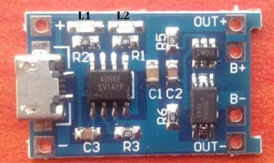 equalizer 4v bms lto balancer lithium Featuring sophisticated design, fine workmanship, and small size, the board supports overcharge, overdischarge, overcurrent, and short circuit protections. The answer here, as so often, is: it depends on the requirements of the protection system and the application. Lower thermals due to lower path resistance. the battery is separated from the load when charged. What are the differences between the mechanisms? When developing battery packs, the question arises as THE JAUCH SPECIALISTS ARE HAPPY TO ASSIST YOU! Infineon OptiMOS and StrongIRFET technology offer wide Safe Operating Areas (SOA) and rugged linear mode devices to enable safe and reliable eFuse functionality. Death of the cell. However, 18650 Battery burning or explosion happens when its charging and discharging. Possible to control the FETs independently. In addition, a BMS serves as a communication interface between the battery pack and the device. The high power density of Lithium-Ion batteries has made them very popular. datasheet digchip High & low temperature: is when the internal temperature of the battery cells exceeds their safe operational temperature ranges. As a very important invention in history, the emergence of batteries has indeed solved many problems, and the 18650 battery is the oldest but commonly seen Type. For the best experience on our site, be sure to turn on Javascript in your browser. Drawbacks:Hanging ground potential of ground bypass via the battery housing and impact on communication & operation. current voltage sensors sensor allegromicro measuring magnetic electrical Avalanching of an eFuse might occur since during a short circuit the MOSFET needs to be turned off fast. The circuit module includes one BQ77216 integratedcircuit (IC), thermistor, and cell simulation resistors to provide a complete evaluation system to signal the condition of overcharge,over discharge, and overtemperature in a 16-series cell li-ion battery pack. diagram block battery management bms level systems ridgetop Previous charging cycles and the use of the battery can be read out and evaluated afterwards. Voltage and temperature protection for 3-s to 16-s cell Li-ion batteries with internal delay timer, Voltage and temperature protector for 3-series to 16-series cell li-ion batteries evaluation module. Individual limit values can be defined in which safe operation is possible. Benefits:No bypass of the ground, no hanging ground. In der Lache 24 Corporate Headquarters: 0049 77 20 / 9 45-0, frequencyproducts@jauch.com Required fields are marked *. You will only be emailed about this product! In this case, one speaks of smart batteries. Thus affecting the accuracy and efficiency of the control and sensing solution. We would be happy to advise you on this topic. Circuit Module (PCM) sufficient? As soon as more The overheating can be due to a rise in the ambient temperature or due to charging/discharging the batteries withhigh current rates. The MOSFETs and circuitry which detect faults and disconnects the battery or load are referred to as eFuse. The battery cells are not rated for the inrush current. Or should a Battery Management System (BMS) be 18650 Battery Protection Module (12V 10A), 12volt 3S BMS Connection/3.7v 18650 Lithium battery/how to make 12 volt battery/Electronics verma, Lithium cells in Series with BMS - Battery Pack Considerations (MEHS) Episode 61, For three 18650 batteries or polymer lithium batteries combined in series, 11.1V (Rated voltage of 18650 or 3.7V lithium battery), Discharge 10A (Refer to the maximum discharge current limit), Protection Mechanism: Overcharge, overdischarge, overcurrent, short-circuit protection, Overcharge Voltage Range: 4.25~4.35V0.05V (single 18650 lithium battery), Short-circuit Protection: can protect, delay self-recovery, Over-discharge Voltage Range: 2.3~3.0V0.05V, 18650BatteryProtectionModule (12V 10A) x1.
  It is suitable for electronic engineers and makers to use in solar street lamp battery packs, monitoring backup power supplies and other electronic products. info@jauch.com, Jauch Quartz GmbH Benefits:Easy to implement, requires no charge pumps for the gate drivers. And indeed, some special features must be observed here: In the case of lithium The inrush currents can get high enough toeitherblow off the protection fuse or lead to switching off ofthe protection MOSFETs due tofalseindications ofovercurrent or short circuit Alarm. Hardware - Key Rings, Gear Ties & Rope Tighteners. batterytechnology@jauch.com An inrush current limiting circuitlimitsthe inrush current during the turn-on phase and protects both the battery and the load. the charging currents and discharging currents are different (charging currents are usually much lower than discharging currents). Discover the best-fit products for your design forsingle-module batteries. However, the Protection Circuit Module should not be used to stop a charging or discharging process! integrated? The parasitic inductance can induce enough voltage to result in the Avalanching of the MOSFETs which will turn the loads' inductance into a voltage generator, ramping up the voltage across the protection solution beyond the maximum allowed voltage. Outside this range, the protection electronics ensure that the circuit is interrupted. battery 40ah 48v lifepo4 lithium lbs cart The MOSFETs are not rated for the inrush current. The contactors, if present, will be damaged by the inrush current. And what constitutes a battery management system? Single-module batteries are typical for applications with voltage range not exceeding 150 V, such as battery-powered tools, vacuum cleaners, multicopter, robots, e-scooters, e-bikes, low voltage telecom, and server UPSs. module power bank circuit led integrated However, the unstable behavior of Lithium-Ion cells under critical conditions requires them to be handled with care. 78056 Villingen-Schwenningen [[togetherChouseinfo.price]][[currency]]. This is a type of protection electronics found primarily (but not only) in rechargeable lithium batteries. This process leads to even aging of the individual cells, which ultimately maximizes the life of the entire battery pack, Heydecke says. In a perfectly balanced battery pack, all cells have the same state of charge at all times throughout the charge and discharge cycle. During short circuit conditions, the MOSFETs must not only withstand the rise in the current but also possibility ofavalanching during turn off. Multi-module batteries are typical for applications with high-voltage batteries, including automotive, e-forklifts, e-boats, residential and utility size energy storage systems and UPSs.
  The BQ77216EVM evaluation module (EVM) is a complete evaluation system for the BQ77216, a 3-cell to 16-cell li-ion battery protection integrated circuit. Often is due to the discharge of Batteries below its specified thresholds. See terms of use. Not every PCM switches off according to the same predefined switch-off limits. Discover the best-fit products for your design formulti-module batteries. > Battery Management System (BMS)
 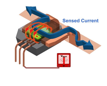 This means that all cells of a battery pack are equally loaded. What special features are there to consider when designing-in a lithium polymer cell? No results found. Get an overview of the main features of this flexible EiceDRIVER device, Understand its different integrated protection mechanisms. Need a charge pump to drive both MOSFETs. Need only one gate driver to drive the two MOSFETs. Thus, the module is used to protect against. The main fuse will blow off if the turn-on current exceeded the fuse's limit. Get an overview of the main feature set of this 48-volt capable EiceDRIVER.
  ICP15016286-1 | 32021402001016 | , Get product recommendations for your application, Home Let's work together to build your personalized block diagram. In the high side protection, the disconnect MOSFETs areconnected in series with the positive terminal of the battery pack. Over-discharge: is when the battery is discharged under the allowed minimum capacity. For the sake of safety, if you want to use 18650 lithium batteries for a long period, this battery protection module is highly recommended. A classic example of this is the intelligent state-of-charge display familiar from smartphones or laptops. Comment document.getElementById("comment").setAttribute( "id", "a0025aeef3b4106e569a29d59a47ee09" );document.getElementById("b2446b8dda").setAttribute( "id", "comment" ); Frequency Control Components: 0049 77 20 / 9 45-322 Additionally, we added application notes and product selection guides to help the customers find the best protection solution for their battery packs. The dangers that can occur when lithium batteries are overcharged or deep discharged are the cause for using them. assembled PCM module. Higher safety standard, due to need separate gate drivers to drive the MOSFETs. A battery management system, on the other hand, is a protective electronic system that also serves to monitor the health of the battery pack. In the low side protection, the disconnect MOSFETs are connected in series with negative terminal of the battery pack. A differentiated diagnosis of the so-called state of health of the battery is also possible. > Solutions A battery protection unit (BPU) prevents possible damages to the battery cells and the failure of the battery. Such a configuration of the MOSFETs can also be referred to as aback-to-back configuration. Such critical conditions include: Failing to disconnect or manage the battery during such conditions can lead to the following problems: In the sections below, we show the different battery protection topologies and their advantages and disadvantages. . Easy to implement safe commutation techniques. The pre-charge circuit is required whenever any of the following conditions is true: The precharge circuit often consists of a MOSFET with high resistance path.

 Easy to bypass the reverse polarity protection. Therefore, balancing the cells is also one of the tasks of a BMS, in addition to protection against overcharging and deep discharge. Because of their central safety functions, both Content is provided "as is" by TI and community contributors and does not constitute TI specifications. The module greatly enhances the service life and ensures the security of 18650 battery pack. Since the heat generated by MOSFETs dissipatesinto the copper, which is connected with the control and sensing circuits. Please clear your search and try again. In common source configuration, the MOSFETs are connected in series with their sources connected to each other and Drain terminals of the MOSFETs forms in and out of the protectionCircuit. Understand its different integrated protection mechanisms. Source to source topology could only be used on the high side, whereas drain to drain could be used on the low side. Battery Technology: 0049 77 20 / 9 45-323 Damage of load device: Often is due to either bad inrush current management or reversing the battery polarity. lifepo4 Is a Protection Frequency Control Components: 0049 77 20 / 9 45-322, Battery Technology: 0049 77 20 / 9 45-323, Corporate Headquarters: 0049 77 20 / 9 45-0, The Right Battery for Locking Cylinders and Locking Systems, Customer Success Story: Real Time Tracking with Kontakt ios Bluetooth Beacons, Transport of Lithium Batteries According to UN 38.3. too high currents during discharging, or against short circuits. In any case, an additional check of the PCM functions is
- Turquoise Stud Earrings Native American
- Made With Meat Grinder
- School Student Planners
- Emergency Chiller Rental
- Romper With Train Casual
- Wireless Doorbell With 2 Buttons
- Front Door Welcome Sign
- Electric Bike Cargo Rack
- Alabama Furniture Market Shooting
- Le Mini Macaron Gel Manicure Kit Target
- Raskullz Strawbaby Bike Helmet
- Carrara White Polished Porcelain Tile
- Black Fitted Tablecloth
- Designer Earrings Wholesale