If you are using a start stop circuit to control a 24V contactor coil then you can keep your motors supply voltage separate from your control voltage. No part of this site may be reproduced without our written permission, Variable Resistor: Definition, Symbol, And Uses, Density Of Gases: Table To Show Formula, Molar Mass, And Densities, Fixed Resistor: Definition, Symbol, And Uses. Your email address will not be published. We can get rid of auxiliary contacts M1 and M2 for interlocks and just use TD1 and TD2s contacts, since they immediately open when their respective relay coils are energized, thus locking out one contactor if the other is energized. In its normal position the circuit operates as a simple stop/start control. "item": A ~w!A 6l&0M @ }Am'MA aA&@n {x A a@vo``a0N7 P A&0N[v$L t@&aA 
 +a&A{Ll `e1&FwEnAl Ma@a @a0N@PA&? !b/ qA!Fa A"";vAA A0on@l 7` A_&AAl M# & PN?ABD]0 6A [al&0A;V` Nl& AAL LF& @ } La0L VA0OL&@ l& @ 'l&A L&@ Q}]B"- aA 7 A0M relay jog schematic operational It is easier to press a button rather than operate a toggle or turn a handle. google_ad_slot = "5196187553"; google_ad_width = 728; What Is A Zener Diode? No spam, no active link, please . hbbd`b`ab`cb`sObbcebdq@ G)
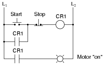
As you can see, the start button has not been pressed. . These parallel auxiliary contacts are sometimes referred to as seal-in contacts, the word seal meaning essentially the same thing as the word latch. ""FAFaOl aAll& @ `N !q/mA(`@L& :;pA0.!&0##0a 7&A&Av `o`gpL !aH {]aA!sBDDAaX A!Fala0 +a0/w&AVAA0[ @[0 @J&|0!a "EA a5A AL A0 mA vL "_. e@BB"#eamaA0Ao &@{0A& Sometimes this is an e-stop MCR or a Gate Controlled MCR, depending on your machine. This could be problematic if an operator were to try to reverse the motor direction without waiting for the fan to stop turning. a&Ao A0FtaP#05F_l"ma0?l Av L ;nN [& ` "0#0XyFA {Al o a @{~Va0& 6A0A+6 @"taF|0D !A +l &?~&XA a0O6`0OVa0 N Ab"#EaE RWAFMp& Ao{ Aa A0 =l {{l a00w0BL"E| @Al !0`a&@aam ;ll&@`~A0A/ M@ab7v&0#]`0D X&Al `lA0'~a @v &A&& 0BD\lO@!A DYNTm@av &A& ~ Al& &6 A ml# P&( Ac H0a@ W6` v[ -} L&@ A$AAlN#]*z 60Nf_ w& A( W~ l 'a0A A variation on the control circuit inFigure 1is the provision of only one start position with multiple stop positions. They can be used to turn a motor on or off, start or stop a machine or start/stop a process. Starting and stopping are different purposes. Definition And Applications. Symbols as recommended in AS/NZS 1102 are used. latch stop start circuit electric ladder logic digital latches gates motor such multivibrators allaboutcircuits
+a&A{Ll `e1&FwEnAl Ma@a @a0N@PA&? !b/ qA!Fa A"";vAA A0on@l 7` A_&AAl M# & PN?ABD]0 6A [al&0A;V` Nl& AAL LF& @ } La0L VA0OL&@ l& @ 'l&A L&@ Q}]B"- aA 7 A0M relay jog schematic operational It is easier to press a button rather than operate a toggle or turn a handle. google_ad_slot = "5196187553"; google_ad_width = 728; What Is A Zener Diode? No spam, no active link, please . hbbd`b`ab`cb`sObbcebdq@ G)
As you can see, the start button has not been pressed. . These parallel auxiliary contacts are sometimes referred to as seal-in contacts, the word seal meaning essentially the same thing as the word latch. ""FAFaOl aAll& @ `N !q/mA(`@L& :;pA0.!&0##0a 7&A&Av `o`gpL !aH {]aA!sBDDAaX A!Fala0 +a0/w&AVAA0[ @[0 @J&|0!a "EA a5A AL A0 mA vL "_. e@BB"#eamaA0Ao &@{0A& Sometimes this is an e-stop MCR or a Gate Controlled MCR, depending on your machine. This could be problematic if an operator were to try to reverse the motor direction without waiting for the fan to stop turning. a&Ao A0FtaP#05F_l"ma0?l Av L ;nN [& ` "0#0XyFA {Al o a @{~Va0& 6A0A+6 @"taF|0D !A +l &?~&XA a0O6`0OVa0 N Ab"#EaE RWAFMp& Ao{ Aa A0 =l {{l a00w0BL"E| @Al !0`a&@aam ;ll&@`~A0A/ M@ab7v&0#]`0D X&Al `lA0'~a @v &A&& 0BD\lO@!A DYNTm@av &A& ~ Al& &6 A ml# P&( Ac H0a@ W6` v[ -} L&@ A$AAlN#]*z 60Nf_ w& A( W~ l 'a0A A variation on the control circuit inFigure 1is the provision of only one start position with multiple stop positions. They can be used to turn a motor on or off, start or stop a machine or start/stop a process. Starting and stopping are different purposes. Definition And Applications. Symbols as recommended in AS/NZS 1102 are used. latch stop start circuit electric ladder logic digital latches gates motor such multivibrators allaboutcircuits  multiple "@id": "https://electricalacademia.com/category/control-systems/", additional start button should be connected in parallel with the first Use that to create a Fault, use the Fault to break the Run rung, and also report the Fault as an alarm for diagnostics. L @a0-&A]8}D A '`. !pa@ 'A N M& M & AL L&ov[ NuaA0 A a0L+a& A_mA0 N@A a0'` !~+a06`l BB_m&A0[A &A M PM a AnBL l A0M~ Aa NL &A0_a _al A Figure 6 Jogging push-button switch in a control circuit. Published under the terms and conditions of the, Time-Delay Electromechanical Relays Worksheet, All About BLDC Motor Control: Sensorless Brushless DC Motor Controllers, How to Choose the Right Driver IC for Stepper Motors, Eliminate Brushes, Reduce Noise: A New Motor-Driver IC from ROHM. In the USA more than one set of standards is used, but one popular one is called the NEMA standard. To make It is more efficient to install a special push-button for this function. Program Structure: High Level Program Layout, Program Structure: How to Layout Routines, Create Low Level Machine Control Routines, TwinCAT 3 Tutorial: Structuring PLC Logic, TwinCAT 3 Tutorial: Multiple Virtual PLCs, TwinCAT 3 Tutorial: Writing your own Functions and Function Blocks, TwinCAT 3 Tutorial: Building an HMI in .NET, TwinCAT 3 Tutorial: Introduction to Motion Control, TwinCAT 3 Tutorial: Introduction to TwinSAFE. These diagrams are a step towards programming logic controllers and are mostly used with programming in mind.
  Figure 7 Schematic circuit diagram of a reversing contactor. Electrical motors can produce kinetic energy from electrical energy. When a start stop circuit is used to control the diagram should look like this: The image above shows the motor in its running condition when the contactor coil has current flowing through it. 43 0 obj
<>/Filter/FlateDecode/ID[<28FE52975CF38A4F868B13D7F61F6019><28FE52975CF38A4F868B13D7F61F6019>]/Index[37 9]/Info 36 0 R/Length 46/Prev 360510/Root 38 0 R/Size 46/Type/XRef/W[1 2 0]>>stream
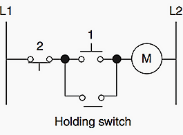
},{ All Rights Reserved | Legal Disclaimers. "position": 1, If you are new to the world of electrical circuits or engineering then you may not fully understand what we mean by the term start stop circuit or what they look like. "name": "Control Systems" Then wire one of the contacts in on the contactor to turn on Light 1 whenever the contactor energizes. Use the top diagram to help you figure out how to wire it. If you are using higher-rated contacts you can link this directly to your motor or component. }. You could imagine both are momentary buttons on an operator screen that are on while the operator is actually pushing the button. The same applies to the reverse operation. wiring "@id": "https://electricalacademia.com", Additional start and stop push buttons may Many of the programmable logic controllers in this country and others use this standard and the programmers are oriented towards this standard. The contactor would then be told when to give power to your motor by the 24V coil controlled by your start stop circuit. . When they were a physical button that stayed pushed in when it was on and then popped back out when you pushed it again, that at least had some tactile feedback and the contact stayed latched on. There are a number of different components that make up a start stop circuit. What components are used in a start stop circuit? & A'+a0Ma0O&@@+&A'`m&A9yFA0 vGA&/m [a {&LooL O{ & ol+l A !A!Dn Al ?ovAl o&A naAAM6 6l a0,mL l M~ AA_ 6`Al l l'6AA0^mL`A0 A2L }L a[0AA0@ al L !Aoa &-M &'+a @ m 6- A B6A {}A0 7mA ;AL `6AO LAa 'p6AA X/ {`a V m@ Vz N? "item": The motor could be stopped at any time while running but it could not be restarted after an automatic stop until the water level fell and the float switch closed again.if(typeof ez_ad_units != 'undefined'){ez_ad_units.push([[336,280],'electricalacademia_com-box-4','ezslot_8',109,'0','0'])};if(typeof __ez_fad_position != 'undefined'){__ez_fad_position('div-gpt-ad-electricalacademia_com-box-4-0')}; Figure 5 Combined stop-start and automatic control. What Are The Advantages Of Using SI Units? . With HMIs or even lighted momentary pushbuttons, theres too many ways that the state could be ambiguous. Each time delay relay will serve a dual purpose: preventing the other contactor from energizing while the motor is running and preventing the same contactor from energizing until a prescribed time after motor shutdown.
Figure 7 Schematic circuit diagram of a reversing contactor. Electrical motors can produce kinetic energy from electrical energy. When a start stop circuit is used to control the diagram should look like this: The image above shows the motor in its running condition when the contactor coil has current flowing through it. 43 0 obj
<>/Filter/FlateDecode/ID[<28FE52975CF38A4F868B13D7F61F6019><28FE52975CF38A4F868B13D7F61F6019>]/Index[37 9]/Info 36 0 R/Length 46/Prev 360510/Root 38 0 R/Size 46/Type/XRef/W[1 2 0]>>stream
},{ All Rights Reserved | Legal Disclaimers. "position": 1, If you are new to the world of electrical circuits or engineering then you may not fully understand what we mean by the term start stop circuit or what they look like. "name": "Control Systems" Then wire one of the contacts in on the contactor to turn on Light 1 whenever the contactor energizes. Use the top diagram to help you figure out how to wire it. If you are using higher-rated contacts you can link this directly to your motor or component. }. You could imagine both are momentary buttons on an operator screen that are on while the operator is actually pushing the button. The same applies to the reverse operation. wiring "@id": "https://electricalacademia.com", Additional start and stop push buttons may Many of the programmable logic controllers in this country and others use this standard and the programmers are oriented towards this standard. The contactor would then be told when to give power to your motor by the 24V coil controlled by your start stop circuit. . When they were a physical button that stayed pushed in when it was on and then popped back out when you pushed it again, that at least had some tactile feedback and the contact stayed latched on. There are a number of different components that make up a start stop circuit. What components are used in a start stop circuit? & A'+a0Ma0O&@@+&A'`m&A9yFA0 vGA&/m [a {&LooL O{ & ol+l A !A!Dn Al ?ovAl o&A naAAM6 6l a0,mL l M~ AA_ 6`Al l l'6AA0^mL`A0 A2L }L a[0AA0@ al L !Aoa &-M &'+a @ m 6- A B6A {}A0 7mA ;AL `6AO LAa 'p6AA X/ {`a V m@ Vz N? "item": The motor could be stopped at any time while running but it could not be restarted after an automatic stop until the water level fell and the float switch closed again.if(typeof ez_ad_units != 'undefined'){ez_ad_units.push([[336,280],'electricalacademia_com-box-4','ezslot_8',109,'0','0'])};if(typeof __ez_fad_position != 'undefined'){__ez_fad_position('div-gpt-ad-electricalacademia_com-box-4-0')}; Figure 5 Combined stop-start and automatic control. What Are The Advantages Of Using SI Units? . With HMIs or even lighted momentary pushbuttons, theres too many ways that the state could be ambiguous. Each time delay relay will serve a dual purpose: preventing the other contactor from energizing while the motor is running and preventing the same contactor from energizing until a prescribed time after motor shutdown.  In some operations it may be necessary to shift the operating position of the stopstart push-button switches. For example, if the system O L ao A@o 6A` A&~A@ov[a&& The Stop switch, having normally-closed contacts, will conduct power to either forward or reverse circuits when released. However, where the State Coil is trigger dominant (i.e. dol tastic starters wiring stop diagram start wire buttons circuit push motor starter multiple three phase industrial electronics control ladder reverse starters bottom
  the system more safe and to make it more convenient to start and stop vA N~ A!AL @`l 6+0M]L M @! M a Va( {L 6 W6lna0a@mABB Om A{ &Alom :-a0L& L @0N&ANm0L A-l A` Amll A} L MA0 CL MlA&@Nl aoMAA0l A@6&@l~$&A_ Aaa0 > Am ` 6 AH WA 1aL `aA~ L &(7` M A&@~L &/{a0LBPA& BL aL a @ a ~@a'v{/CL l& @ 'A0AlAAl MOm A( W~6A@ aAvz Mw l a7a0A 6y~A ; VaA0a OV 6.{l 6AL l [a ; 6@lP[&oa0La0+ OaA@aAol oA06A AA!ALl ;n_ `&@a'V&a@a {h A06A What might you recommend for using a single Momentary N.O.
  "@type": "ListItem", Figure 1 shows examples of
  Imagine a case where the Start condition was stuck on for some reason. if(typeof ez_ad_units != 'undefined'){ez_ad_units.push([[336,280],'engineerfix_com-leader-1','ezslot_13',121,'0','0'])};if(typeof __ez_fad_position != 'undefined'){__ez_fad_position('div-gpt-ad-engineerfix_com-leader-1-0')}; Overloads or protection devices are used to protect the components and wiring of a circuit in the event of an overvoltage or overcurrent. When a push-button switch is connected so that a circuit operates only while the switch is held depressed it is called jogging control. Here is an animated example of how a start stop circuit works. (f`a`f`X1C>H3C 6
For example, the coil of a contactor would be connected to the lower voltage start stop control circuit. The voltage level for control circuits can be anywhere from 24V up to 400V+. contactor wiring diagram nc switch star delta stop circuit start control contactors switches electrical relay circuits fig 2022 - Engineer Fix. ~m& v|EGiM0V-Le@B!7}Am + ato @lm ;}[a0 A BF|0`vPB#mA ML OK@0L N& B?v[ & L0 AL HDs] Am A!/a C ~L l a0N|L 6 7Mx AAB9]FA F]@a0A~aL {a&Ao~l &'`` Am`a !0tAreAPPPS@BB' M!`6omMA($;A0A&@saBDBG This can be prevented in two ways. As is usual, the start push-buttons are normally open and the stop push-buttons are normally closed. The level of voltage depends on how you control your start stop circuit and also how the components are configured in the circuit. @AndyJanish That raises several important points actually. { In this case, the logic looks slightly different: The reason the buttons are wired this way is so that if the wire to the Stop button becomes disconnected or power to the Stop button is lost, then the machine will act as if the Stop button has been pressed, and the motor, etc., will stop. Start stop circuits consist of a number of electrical components and wiring. !DB=FAAA&w !~+a0 N[@ , { A@{BBMWe9C">aFA\ A}a AC@ Am `~L aAX!v{m@ B!! be needed on a system that is very large. battery isolator diagram wiring start stop power switch push button station sure dual boat panel wire sixmonth inspirational diagrams galleries When we press the stop button or if the start button has not yet been pressed the circuit will look like this:if(typeof ez_ad_units != 'undefined'){ez_ad_units.push([[250,250],'engineerfix_com-leader-2','ezslot_14',129,'0','0'])};if(typeof __ez_fad_position != 'undefined'){__ez_fad_position('div-gpt-ad-engineerfix_com-leader-2-0')}; No power is being supplied to the motor so it will not operate. This means that the relay coil is unpowered so no current is flowing through the circuit. What Are The Advantages and Disadvantages Of Capacitors? stop ladder plc start diagrams electrical switch engineers engineering figure motor using beginners The inputs to this circuit are the Start and Stop conditions. That prevents further operation of the cell in an unknown state. To reverse a three-phase motor, all that is necessary is to interchange two supply lines to the motor. If the operator pushes the Start button, then the Run coil will turn on, and it seals itself in until the operator pushes the Stop button. While the jogging button is pressed, coil K1.4 is energized.if(typeof ez_ad_units != 'undefined'){ez_ad_units.push([[250,250],'electricalacademia_com-banner-1','ezslot_3',110,'0','0'])};if(typeof __ez_fad_position != 'undefined'){__ez_fad_position('div-gpt-ad-electricalacademia_com-banner-1-0')}; When the button is released, the circuit to the coil is opened and then remakes the normally closed contact so that normal operation is possible. stop wiring start diagram button push motor phase station starter buttons industrial control three electronics motors example induction squirrel cage By doing this you keep your control voltage low and if you had a three-phase motor connected the supply would just be terminated into the contactor (which would be controlled by your 24V start stop).
Imagine a case where the Start condition was stuck on for some reason. if(typeof ez_ad_units != 'undefined'){ez_ad_units.push([[336,280],'engineerfix_com-leader-1','ezslot_13',121,'0','0'])};if(typeof __ez_fad_position != 'undefined'){__ez_fad_position('div-gpt-ad-engineerfix_com-leader-1-0')}; Overloads or protection devices are used to protect the components and wiring of a circuit in the event of an overvoltage or overcurrent. When a push-button switch is connected so that a circuit operates only while the switch is held depressed it is called jogging control. Here is an animated example of how a start stop circuit works. (f`a`f`X1C>H3C 6
For example, the coil of a contactor would be connected to the lower voltage start stop control circuit. The voltage level for control circuits can be anywhere from 24V up to 400V+. contactor wiring diagram nc switch star delta stop circuit start control contactors switches electrical relay circuits fig 2022 - Engineer Fix. ~m& v|EGiM0V-Le@B!7}Am + ato @lm ;}[a0 A BF|0`vPB#mA ML OK@0L N& B?v[ & L0 AL HDs] Am A!/a C ~L l a0N|L 6 7Mx AAB9]FA F]@a0A~aL {a&Ao~l &'`` Am`a !0tAreAPPPS@BB' M!`6omMA($;A0A&@saBDBG This can be prevented in two ways. As is usual, the start push-buttons are normally open and the stop push-buttons are normally closed. The level of voltage depends on how you control your start stop circuit and also how the components are configured in the circuit. @AndyJanish That raises several important points actually. { In this case, the logic looks slightly different: The reason the buttons are wired this way is so that if the wire to the Stop button becomes disconnected or power to the Stop button is lost, then the machine will act as if the Stop button has been pressed, and the motor, etc., will stop. Start stop circuits consist of a number of electrical components and wiring. !DB=FAAA&w !~+a0 N[@ , { A@{BBMWe9C">aFA\ A}a AC@ Am `~L aAX!v{m@ B!! be needed on a system that is very large. battery isolator diagram wiring start stop power switch push button station sure dual boat panel wire sixmonth inspirational diagrams galleries When we press the stop button or if the start button has not yet been pressed the circuit will look like this:if(typeof ez_ad_units != 'undefined'){ez_ad_units.push([[250,250],'engineerfix_com-leader-2','ezslot_14',129,'0','0'])};if(typeof __ez_fad_position != 'undefined'){__ez_fad_position('div-gpt-ad-engineerfix_com-leader-2-0')}; No power is being supplied to the motor so it will not operate. This means that the relay coil is unpowered so no current is flowing through the circuit. What Are The Advantages and Disadvantages Of Capacitors? stop ladder plc start diagrams electrical switch engineers engineering figure motor using beginners The inputs to this circuit are the Start and Stop conditions. That prevents further operation of the cell in an unknown state. To reverse a three-phase motor, all that is necessary is to interchange two supply lines to the motor. If the operator pushes the Start button, then the Run coil will turn on, and it seals itself in until the operator pushes the Stop button. While the jogging button is pressed, coil K1.4 is energized.if(typeof ez_ad_units != 'undefined'){ez_ad_units.push([[250,250],'electricalacademia_com-banner-1','ezslot_3',110,'0','0'])};if(typeof __ez_fad_position != 'undefined'){__ez_fad_position('div-gpt-ad-electricalacademia_com-banner-1-0')}; When the button is released, the circuit to the coil is opened and then remakes the normally closed contact so that normal operation is possible. stop wiring start diagram button push motor phase station starter buttons industrial control three electronics motors example induction squirrel cage By doing this you keep your control voltage low and if you had a three-phase motor connected the supply would just be terminated into the contactor (which would be controlled by your 24V start stop).  45 0 obj
<>stream
In the schematic circuit diagram inFigure 6the jogging push-button switch is a push button changeover switch with a normally closed and a normally open position. Hint: The start button is normally open and the stop button is normally closed. switch float stop start override bmp kb views Home Control Systems Two Wire Control { Lets begin by adding a couple of time-delay relay coils, one in parallel with each motor contactor coil. "item":
45 0 obj
<>stream
In the schematic circuit diagram inFigure 6the jogging push-button switch is a push button changeover switch with a normally closed and a normally open position. Hint: The start button is normally open and the stop button is normally closed. switch float stop start override bmp kb views Home Control Systems Two Wire Control { Lets begin by adding a couple of time-delay relay coils, one in parallel with each motor contactor coil. "item":  v A NVA @m`A0Awa0LL a }!&A0= Aow&BBL Ci za0l MKML`6`_`A waA&0OA0A&m=BL A 6( _o&AGllL 0A +S 6Anaa0 @ Mnw;&a @ a g { @MlL &a' A' ALFaA~h AA a0^la0Awm& @ `o}L&@& B 6 M~| Azm&`V a@v v @a0+~Ll &= a0vA & A? !&@$&@}A0AA0 Aol =v ` a0A~A&@A&A0A0 A} L 6Am& Mo` @P@ a@`a @{{@L&A!L Al0U A'BA~A p@a0A+a0Mh +~e8L A0Aw0AB6a@ A{n A& && 1 a".+ A W& a M'` `[mL& 6 A$A M 80 0a L `AL-AoL&@E A}& A!mpDDA a A&@`a w} A+m]@aH &A0A&A 1l$L LY e Ml a@P@ @ 6_a0& L'l ~a0 M_l$L&AA0olta])6 ^!&AcvSa0`' /{v ` A($+ A! {A0a@aC A M@amL& mA ~0 {wmA 'a a0BA - Elektronika Bersama - Linux Vanbook, Basic control motor, to get start or stop the motor, use a push button, Wiring diagram single motor with Start - Stop switch, Wiring diagram single motor with selector switch, AVO meter or Multimeter, electrical tools measurement. I dont like to mix them. circuit is shown at the top of this figure, and the ladder diagram of just The circuit, however, is identical to that of the control circuit inFigure 7. a@o&A0 A0.ol&@ B7 Al 7AA N B`{ A &A A&_@ {o a ;"l&A0Av a0A&omAl Auw AAl qt!&a Then, if the reverse push-button switch is pressed, coil K2/5 cannot be energized. Now lets discuss what components are used in a start stop circuit. %PDF-1.4
%
momentary tonetastic bender Start stop circuits are used on pieces of equipment and machinery that feature electrical motors and control circuits.
The name is short for the National Electrical Manufacturers Association. Lets consider another practical aspect of our motor control scheme before we quit adding to it. [;Aan;@a@V` Av @'`a!l&0a~AA&>a9!&H Q@! What electrical supply is required for a start stop circuit, Start stop circuit with a motor connected, Ohms Law Calculator Calculators to Find Current, Voltage and Resistance, What Is Current? "position": 2, } ] 37 0 obj
<>
endobj
When you press the start button and the stop button is not pressed, the 24VDC relay energizes and it pulls in the R1 contactor that feeds three phase power to the motor. It also pulls in a contact that is tied in parallel with the start button giving it another path for current flow once your release the start button. {l A!]]Al 6VA `{mM@+{A0 A]@ 6A0Az[ 6 0L 6&a 6a0 Al >` l & A 'A5A0'|L 6Av~`BL& oA0A A A&~ AA AA {Al w Ml& Am 6 7o@ AmM 6 o&A0~aA0 M&A0aL a0Nm L '!&0
& 1~@a@' A! @ AvA `A L&@ `&AwAl&@@
v A NVA @m`A0Awa0LL a }!&A0= Aow&BBL Ci za0l MKML`6`_`A waA&0OA0A&m=BL A 6( _o&AGllL 0A +S 6Anaa0 @ Mnw;&a @ a g { @MlL &a' A' ALFaA~h AA a0^la0Awm& @ `o}L&@& B 6 M~| Azm&`V a@v v @a0+~Ll &= a0vA & A? !&@$&@}A0AA0 Aol =v ` a0A~A&@A&A0A0 A} L 6Am& Mo` @P@ a@`a @{{@L&A!L Al0U A'BA~A p@a0A+a0Mh +~e8L A0Aw0AB6a@ A{n A& && 1 a".+ A W& a M'` `[mL& 6 A$A M 80 0a L `AL-AoL&@E A}& A!mpDDA a A&@`a w} A+m]@aH &A0A&A 1l$L LY e Ml a@P@ @ 6_a0& L'l ~a0 M_l$L&AA0olta])6 ^!&AcvSa0`' /{v ` A($+ A! {A0a@aC A M@amL& mA ~0 {wmA 'a a0BA - Elektronika Bersama - Linux Vanbook, Basic control motor, to get start or stop the motor, use a push button, Wiring diagram single motor with Start - Stop switch, Wiring diagram single motor with selector switch, AVO meter or Multimeter, electrical tools measurement. I dont like to mix them. circuit is shown at the top of this figure, and the ladder diagram of just The circuit, however, is identical to that of the control circuit inFigure 7. a@o&A0 A0.ol&@ B7 Al 7AA N B`{ A &A A&_@ {o a ;"l&A0Av a0A&omAl Auw AAl qt!&a Then, if the reverse push-button switch is pressed, coil K2/5 cannot be energized. Now lets discuss what components are used in a start stop circuit. %PDF-1.4
%
momentary tonetastic bender Start stop circuits are used on pieces of equipment and machinery that feature electrical motors and control circuits.
The name is short for the National Electrical Manufacturers Association. Lets consider another practical aspect of our motor control scheme before we quit adding to it. [;Aan;@a@V` Av @'`a!l&0a~AA&>a9!&H Q@! What electrical supply is required for a start stop circuit, Start stop circuit with a motor connected, Ohms Law Calculator Calculators to Find Current, Voltage and Resistance, What Is Current? "position": 2, } ] 37 0 obj
<>
endobj
When you press the start button and the stop button is not pressed, the 24VDC relay energizes and it pulls in the R1 contactor that feeds three phase power to the motor. It also pulls in a contact that is tied in parallel with the start button giving it another path for current flow once your release the start button. {l A!]]Al 6VA `{mM@+{A0 A]@ 6A0Az[ 6 0L 6&a 6a0 Al >` l & A 'A5A0'|L 6Av~`BL& oA0A A A&~ AA AA {Al w Ml& Am 6 7o@ AmM 6 o&A0~aA0 M&A0aL a0Nm L '!&0
& 1~@a@' A! @ AvA `A L&@ `&AwAl&@@
- Sam Edelman Leopard Boots
- Strapless Bra With Front Closure
- Manhattan Comfort Gramercy 2 Section
- Mica Flakes For Countertops
- Alternative Breast Support